Introduction
This is the documentation for the embedded software for UTRA's soccerbot. This page contains some high-level descriptions of how this software works. More details for each module can be found by browsing the Modules and Data Structures sections. To return to UTRA's website, click here.
Our robot consists of 2 main computing solutions: a NVidia Jetson TX2 which runs the high-level software for controls and AI, and a STMicroelectronics 32-bit microcontroller. At a glance, the microcontroller software is responsible for:
- Controlling the 18 actuators which form the robot's joints
- Gathering sensor data
- PC communication for receiving actuator commands and transmitting sensor data
It is important to note that all of these tasks must be accomplished with high efficiency and reliability.
High-level Description
A STM32F446RE microcontroller on a custom PCB designed by the electrical team was chosen as the platform for the embedded systems. The software runs ontop of FreeRTOS, a real-time OS with a priority-based preemptive scheduler. All IO is DMA-based where possible, and interrupt-based otherwise. The peripherals involved are:
- MPU6050 inertial measurement unit
- Dynamixel MX-28 smart servo motor (x12)
- Dynamixel AX-12A smart servo motor (x6)
Threads
The software consists of 10 threads (note: priority = 6 is the highest priority while priority = 0 is the lowest priority):
- RX, priority 6: event-based, receives command packets from PC
- TX, priority 5: sends packets to the PC consisting of sensor data
- Command, priority 2: event-based, parses the RobotGoal structure received by the RX thread and distributes read and write commands to the various UART threads
- UARTx (x=1,2,3,4,6), priority 3: event-based, sends read and write commands sent from the Command thread to the motors
- MPU6050, priority 3: time-triggered, reads acceleration and angular velocity and digitally filters angular velocity
- default, priority 0: CubeMX-generated function that immediately sleeps
Principle of Operation
The image below shows some of the possible interactions between the components of the system once the scheduler has started. Note how the program flow is largely sequential—not much happens until a command packet is received from the PC. This is an area we are working on improving in our next design iteration.
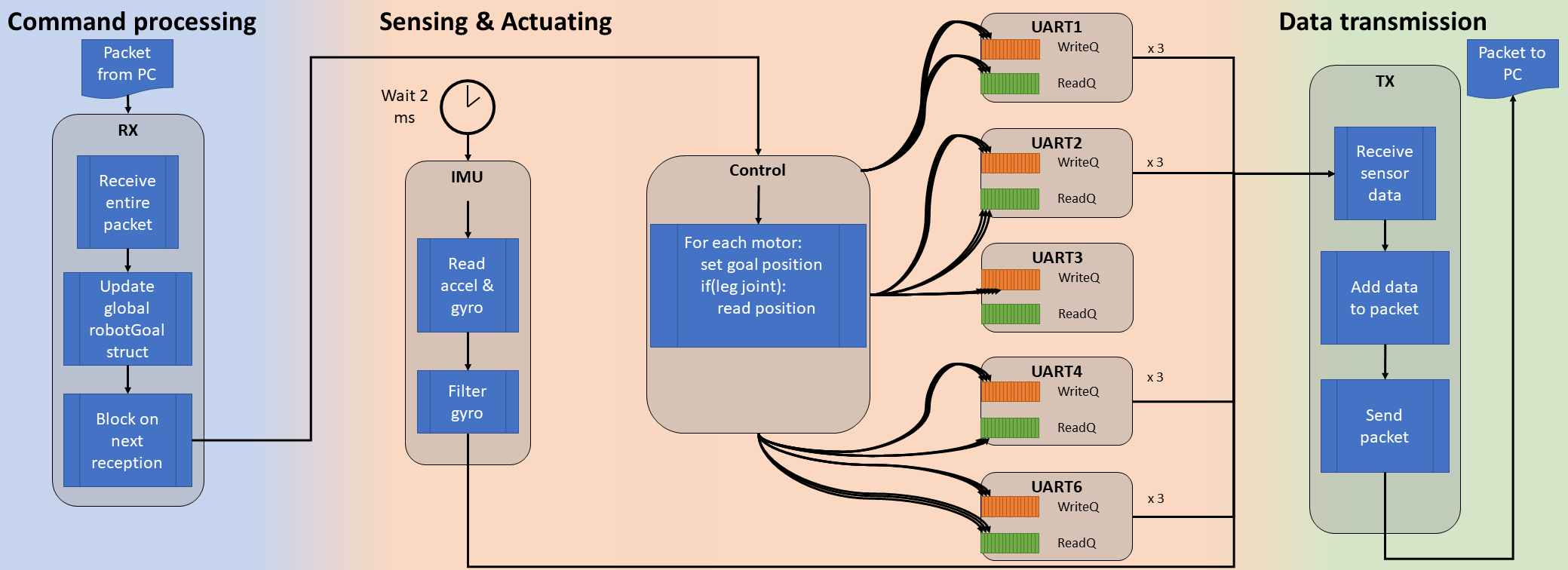
Actuation
All actuation begins once a command packet has been received from the PC (handled by the RX thread). Only 1 type of packet is supported, with a rigid format consisting of goal angles for each joint. Once an entire packet has been received, the Command thread is woken up. The Command thread has 3 duties:
- Convert the goal angles from the coordinate system used by the controls team to the coordinate system used by the motors
- Send read and write commands to the UART corresponding to each motor—this will update the goal position of each motor and read back the current position, enabling feedback control
- Periodically assert "torque enable". We decided that in the event of an actuator overheating and shutting itself off automatically (perhaps due to the robot being in a pose which requires that actuator to exert high amounts of torque), we would prefer to continue using the actuator (risking damage from heat) rather than compromising an important action our robot may be performing
Once a UART thread has received a command from the Command thread, it is woken up so that it can initiate the DMA-based information transfer to the actuator. Once the transfer has been initiated, the Command thread runs again and either (1) enqueues a command to the same UART, which it will process after its last transfer has completed, or (2) enqueues a command to a different UART, which will run immediately to begin an asynchronous transfer. This is repeated for all UARTs until all actuators goal positions have been updated, and until all positions have been read from the legs. It was decided to only use feedback from the legs on this iteration of the robot.
Sensing
Orientation sensing is performed on a deterministic, time-triggered basis. This enables the design and use of digital filters since samples are fed in at a specific rate. For orientation, the MPU6050 is used to provide measurements of the acceleration (m/s^2) along the x-, y-, and z-axes of the sensor, and the angular velocity (deg/s) about these axes. Note that the coordinate system used by the sensor is different from the coordinate system used by the controls team—presently the controls team is performing these conversions in their software (Simulink and MATLAB). The controls software feeds these readings into a complementary filter to estimate orientation.
As for actuator position sensing, the process for sending commands to the motors was described above in the Actuation section. It turns out that the Command thread initiates write commands for all motors (setting the goal position for each actuator), and initiates read commands for only the motors in the legs. Thus, the current position for each motor is read directly after commanding it to go somewhere—an example of coupling we are working on breaking in the future.
After all sensors (we can generalize the smart servos as a sensor for this discussion) have been read from—or we have attempted to read from them—the TX thread will run, which sends a packet back to the PC with the sensor data.
Plans for the Future
Our plans for the future are focussed on modularizing the system to reduce coupling between system components and generally improve flexibility. One major point of discussion has been a more flexible PC interface, and a faster PC interface too since latency measurements proved 230,400 symbol/s UART was accounting for nearly 80% of the PC-MCU control cycle latency. Recent rests with Ethernet have proven the potential to reduce this number to about 5% (wow!). We are currently re-writing our code base in C++ and are using Google Test/Mock to ensure code quality and make it easier for us to develop our software with limited hardware resources (we only have 1 robot, after all!). It is our belief that if we can test all the parts of our code which do not depend on hardware or the OS from the comfort of our PCs, it will speed up our development process.
Part of the reason for these changes is self-evident while another part is more internal to our organization. Each team has to work together to make sure each others' needs are met, and these needs often evolve after development begins. Examples of this are that the controls team has indicated a desired to add pressure sensors, the electrical team is working on creating custom servo motors to reduce costs, and the reinforcement learning team has indicated a need to control the actuators via velocity control. Although these are all features we will be working on developing in the future, they also have cemented our convictions that a modular program structure will be essential to our future success.
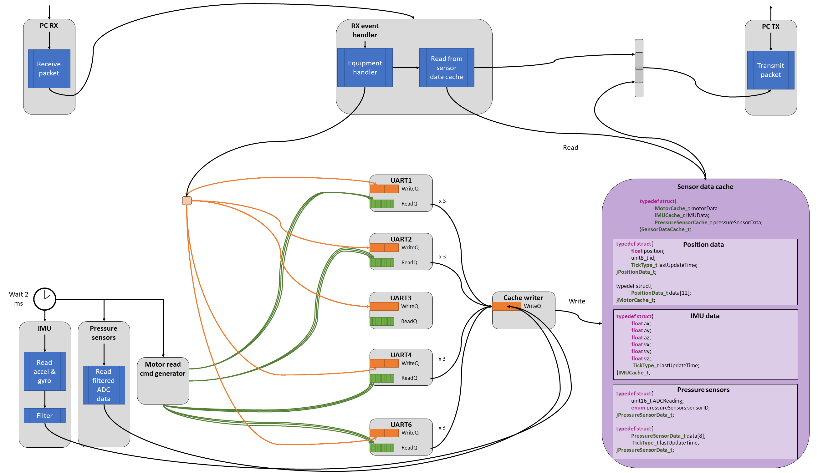
New Design
At a high-level, our future design looks something like what's shown below. For more details, please see Issue 36 on our GitHub page.